
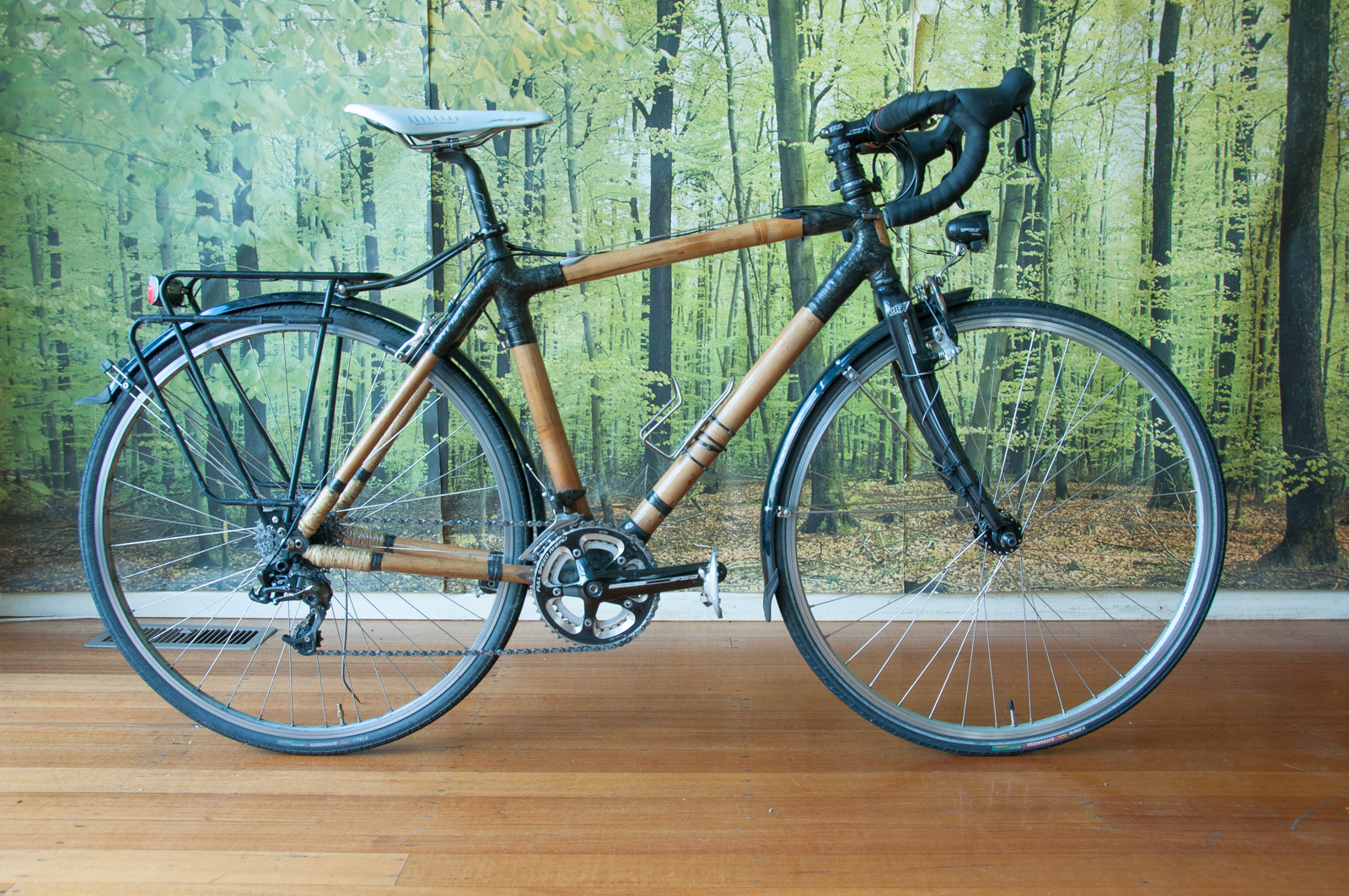
So it’s been 5 years since I built Maisie, my first bamboo bike, and since then she’s morphed from a svelte single-speed cyclocross machine, to a more relaxed and convenient commuter and tourer. It’s amazing how versatile a bamboo frame is – you can drill holes in it, attach things (like cable-stops) with wood screws, and generally tinker with it without the need for welding. The thick walls mean that threads can actually bite in and using things like rivnuts or threaded inserts is relatively easy.
Last year I got rid of my car, so Maisie’s been my primary mode of transport since then, and I’d estimate I do about 150km per week of commuting and getting about.
I’ve taken a bunch of photos of Maisie in her current state, and will go through the various small customisations that I’ve made in order to turn her into a geared, racked and fendered commuter/tourer.
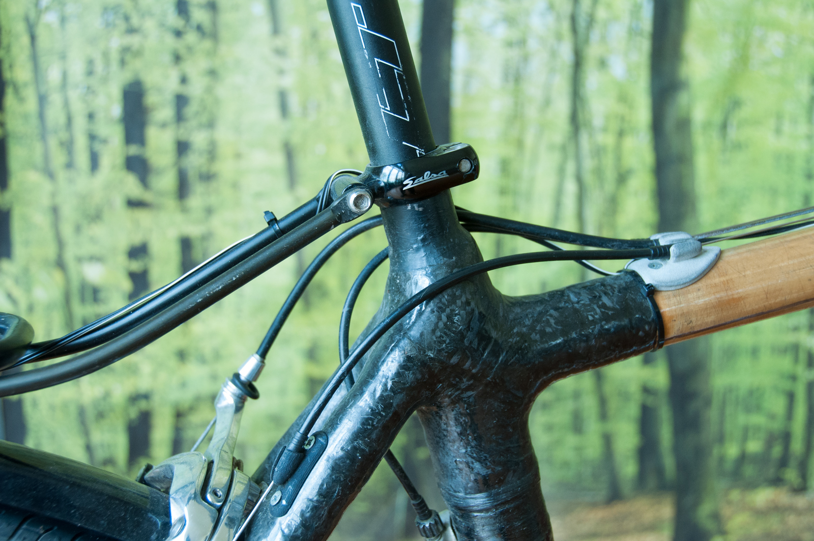
Cable stops for gears and brakes
Adding gears means adding cables and cable stops. Luckily I’m pretty handy with Solidworks and modelled some nice cable stops which could be screwed onto the frame. I got them 3D printed in nylon and aluminium at Shapeways and then attached them to the frame. The barrel adjuster for the rear derailleur I didn’t make – it’s a standard cable-stop (that would normally affix on some down-tube shifter bosses) that I just drilled a hole through and screwed to the frame.


Fender Mounts

I needed a fender mount near the bottom bracket, but didn’t want to drill another hole in the frame, so I lengthened the derailleur pulley bolt and inserted a spacing washer. The entire assembly is attached by a single bolt from inside the fender, through the spacer, pulley and into a threaded rivnut in the seat-tube. The brake-bridge fender mount was supplied with the fenders, which just fits over the calliper bolt. Standard.
Racking it up
Not much was needed to add a rack to the frame, as the drop-outs already had a mounting bolt hole. All I needed was a Salsa Post Lock seat post clamp and the job was done.
Let there be light
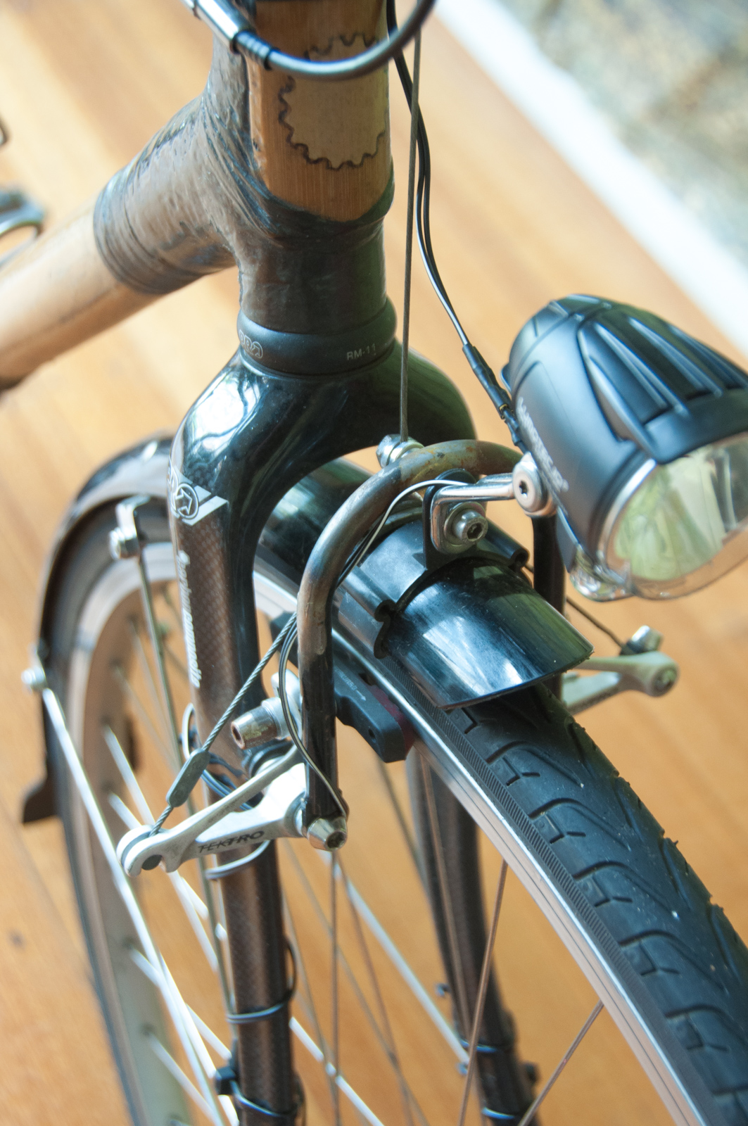
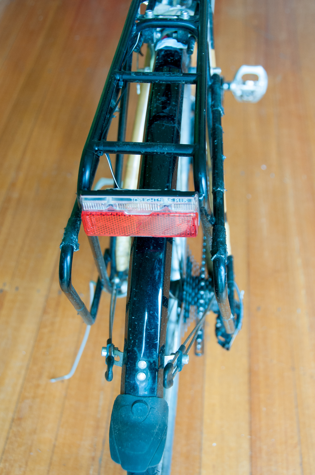
It wouldn’t be a proper commuting bike without a dynamo light, so I bought a new wheel from Commuter Cycles with a SP Dynamo PD-8 in it and wired it up to the top of the line Busch & Muller Lumotec IQ Cyo Senso Plus headlight and a Toplight Line Plus taillight too.
As my fork doesn’t have a crown hole for fenders/lights I mounted it to a u-shaped bracket affixed to the canti-studs. Good mate Scott Symes welded the hourglass to the bracket for me. I should really get around to painting it one day.
It’s absolutely amazing how much a permanent light source changes the way you think about cycling. It’s a total game changer. No more remembering where your USB blinkies are, no having to take them on and off each time you leave your bike locked up somewhere, no having to worry about them going flat. You just get on your bike and ride it, anytime of day or night. Once you get used to this concept it becomes quite a chore to ride a bike without in-built lighting. Viva the light revolution!
How’s she holding up?
Besides some interesting creaking noises when the weather is really hot the frame seems to be maintaining its strength and durability over the long term. There’s been no de-lamination of the carbon, no cracking of the bamboo and despite a few scratches the clear-coat is holding up well. So there’s not much to report on really – it’s a bike, and it still rides like one!


